Wiring Diagram For 2000 Ford F350 Diesel
Crimestopper SP-502 Remote/Alarm Installation for 2000 Ford F250 Superduty, 7.3L Powerstoke Diesel
Below is the wiring diagram I drew up for my install and some pictures showing the wire locations. The wiring diagram is in schematic form. This unit has a lot of features. It includes remote start, turbo timer, remote entry (with separate driver's door unlock), passive starter disable/anti-grind, and dome light supervision. The alarm includes the usual door supervision and shock sensor options and also has 2 way paging so I will be notified on the remote if something nefarious is going on. To utilize all the features, I needed to purchase one extra Crimestopper SP-502 alarm, keyless entry and remote start system.
Application and References Details
** Truck already had remote keyless entry (factory system quite working)
** Truck wiring connections are shaded green
** Relay connections are shaded blue
** Wires with a red "X" were not used in this installation
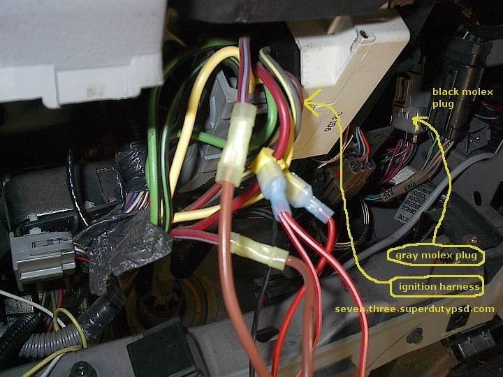
** C218 references the Ford manual plug designation for the gray molex plug
** C217 references the Ford manual plug designation for the black molex plug
I drew this schematic for my truck and it works perfectly. If you decide to use the information presented here, you should verify that it is suitable for your application. All wiring should be verified. Use at your own risk. Note that this drawing is in schematic form.
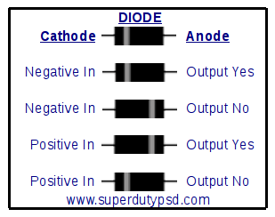
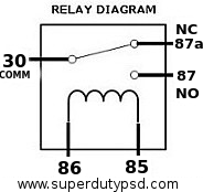
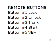
The three images below show how relays and diodes are wired. Also the remote button designatons.
Below are links to tha Crimestopper factory manuals.
Alarm/Remote Start Install (at the end of this page the wiring is laid out in table form)
Location of most wires:
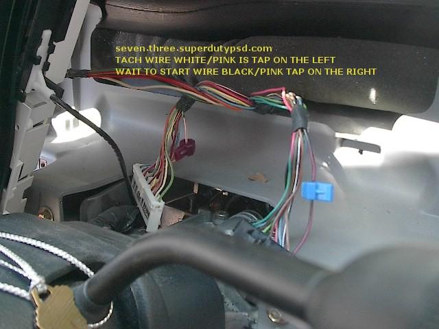
Location of tach and wait to start wires:
- Use caution when taking the instrument cluster out.
- You will need to remove the transmission indicator ware from the steering column.
- Note that some remote start makes do not deal well with Ford's wait to start circuit so a time delay is needed.
- The Crimestopper worked just fine with the WTS circuit, no diodes needed.
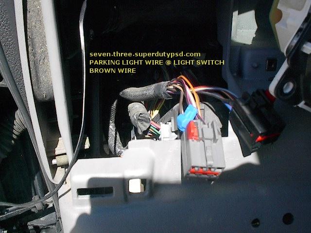
Location of parking light wire:
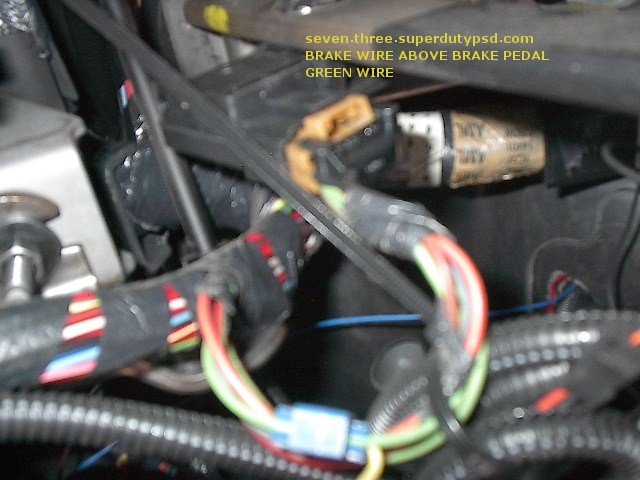
Location of brake wire:
Wiring Diagram In Table Format
| Harness | Harness Wire Color/Function | Wiring Connections | ||
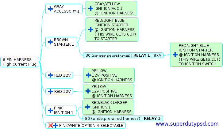
| 6-pin-harness | pink/white ignition 2 | NOT USED | ||
| pink ignition | + red/black larger @ ignition harness | |||
| Relay 1 terminal 86 | ||||
| red 12V positive | + yellow @ ignition harness | |||
| red 12V positive | + yellow @ ignition harness | |||
| gray acc | + gray/yellow @ ignition harness | |||
| brown starter | + red/light blue @ ignition harness (this wire gets hot) to starter | |||
| Relay 1 terminal 30 - to - relay 1 terminal 87A | Red/light blue @ ignition harness (this wire is cut) to ignition switch | |||
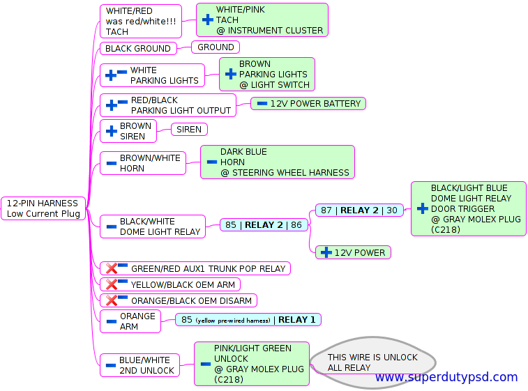
| 12-pin-harness | white parking lights | + brown @ light switch | ||
| black | ground | |||
| white/red tach | white/pink @ instrument cluster | |||
| orange/black (-) oem disarm | NOT USED | |||
| orange (-) starter disable relay coil | Relay 1 terminal 85 | |||
| blue/white (-) passenger unlock | truck pink/light green @ gray molex plug | |||
| blue/black (-) ignition or aux #2 | NOT USED | |||
| green/red (-) aux #1 | NOT USED | |||
| black/white (-) dome light | Relay 2 terminal 85 - to - relay 2 terminal 86 | Relay 2 terminal 87 - to - relay 2 terminal 30 | black/light blue @ gray molex plug | |
| 12V (+) power | ||||
| brown/white (-) horn | dark blue @ steering wheel harness | |||
| brown (-) siren | siren | |||
| green (-) turbo timer | momentary switch (no) | ground | ||
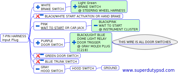
| 7-pin-harness | White (+) brake pedal reset | Light green @ brake pedal | ||
| Pink (-/+) glow plug | black/pink (-) @ instrument cluster | |||
| gray (-) hood switch | hood switch | ground | ||
| green (-) door switch | NOT USED | |||
| purple (-) door switch | black/light blue @ gray molex plug | |||
| Blue (-) trunk switch | NOT USED | |||
| black/white (-) start or hand brake | NOT USED | |||
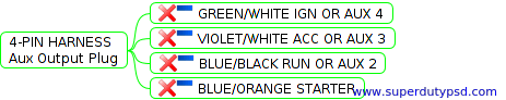
| 4-pin-harness | not used | NOT USED | ||
| blue/orange (-) start output | NOT USED | |||
| violet/white (-) aux #3 | NOT USED | |||
| green/white (-) aux #4 | NOT USED | |||
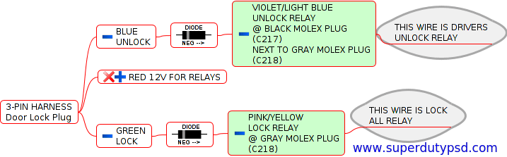
| 3-pin-harness-2 | green (-) lock/(+) unlock | diode | pink/yellow @ gray molex plug | |
| Red (+) for relays | NOT USED | |||
| Blue (-) unlock/(+) lock | diode | violet/light blue @ black molex plug next to gray molex plug | ||
| | | | | |
| | | | | |
| | KEY | | | |
| | NOT USED | | | |
| | TRUCK WIRING | | | |
| | RELAY WIRING | | | |
| | SYSTEM COMPONENT | | | |
BACK
Posted by: perfectorhair.blogspot.com
Source: https://www.superdutypsd.com/crimestopper-sp-502-alarm_with_remote_start-installation.php